Medical Devices, Design & Development, Quality & Testing, Regulation & Standards
Preventing Catheter Connector Disconnections and Infection Risks
Updated
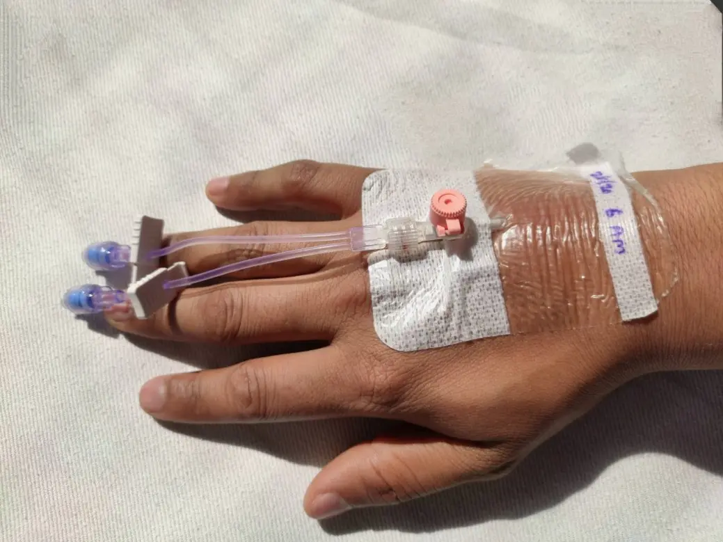
A catheter connector is a small component with a large safety role. It can be the access point for treatment, but also the point at which a line leaks, separates, becomes contaminated, or behaves unexpectedly when a syringe or administration set is disconnected.
Catheter connector disconnection prevention starts before use. Product selection, dimensional compatibility, assembly force, routing, cleaning instructions, displacement behavior, and inspection all need to work together. A connector that is mechanically secure but hard to disinfect creates one type of risk. A connector with good access hygiene but poor resistance to traction creates another.
This article focuses on the design and use controls that help teams reduce separation, leakage, contamination, occlusion-related problems, and—where drainage systems are involved—unintended fluid loss.
Begin with the failure mode, not the connector label
“Catheter connector” covers several different products and clinical systems. A needleless IV connector, a luer lock, a stopcock connection, an enteral fitting, and a connector within a cerebrospinal fluid drainage system do not have the same hazards or performance requirements.
The first practical step is to define what happens if the connection fails. A useful risk review separates at least five outcomes:
- Complete separation: tubing disconnects from a catheter hub, stopcock, extension set, or adaptor.
- Partial disengagement or leakage: the connection remains attached but leaks under pressure, bends, or intermittent movement.
- Fluid-pathway contamination: microorganisms enter through an incompletely closed, poorly disinfected, damaged, or repeatedly accessed connector.
- Flow restriction or occlusion: blood reflux, particulate buildup, valve malfunction, kinking, or incompatible components impair flow.
- Uncontrolled drainage or air entry: in gravity-sensitive drainage systems, an open or separated pathway can alter pressure conditions and cause clinically significant fluid loss.
The consequence should determine design priorities. A peripheral IV extension may need robust repeated access and leak resistance. A high-pressure infusion pathway needs verified pressure capability across the assembled system. An external drainage system requires particularly strong control of connection integrity, line routing, stopcock state, and detection of separation.
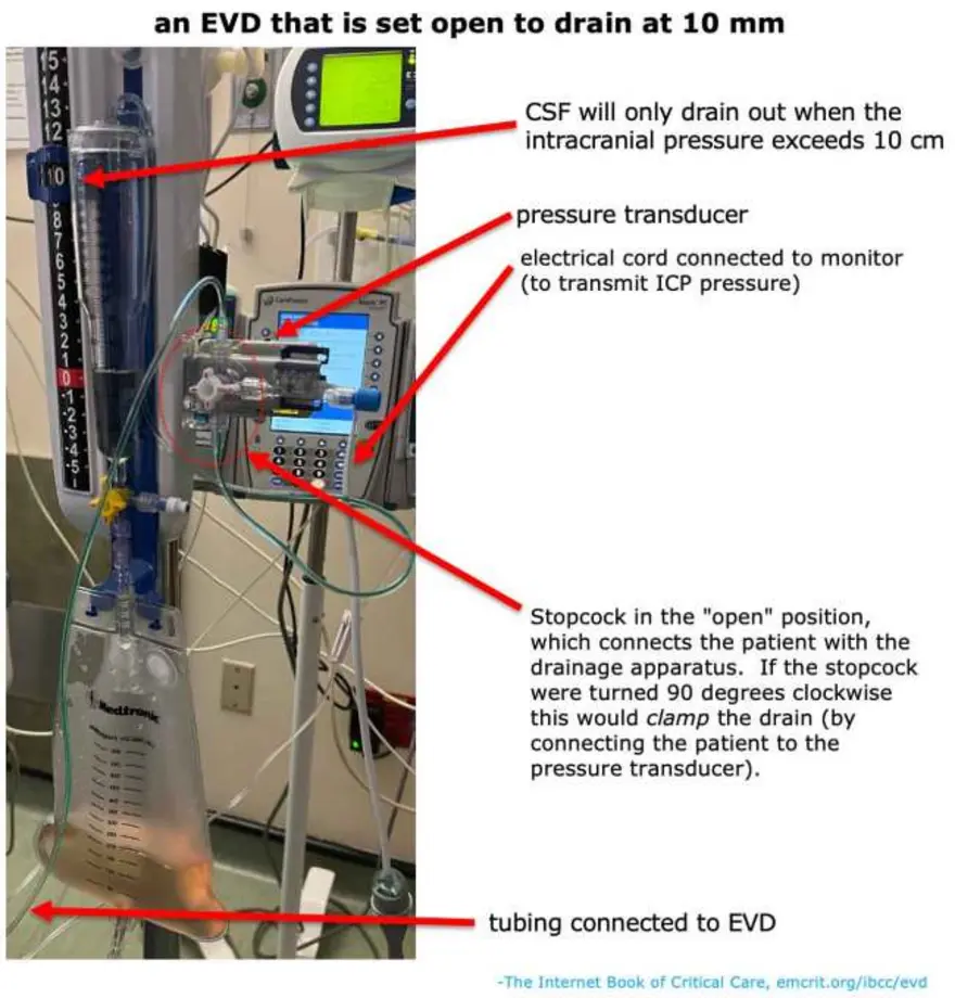
A recent FDA Class I recall involving external drainage and monitoring system tubing illustrates why the system context matters. The identified issue was potential disconnection from patient-line stopcock connectors. Potential harms included infection, cerebrospinal fluid leakage, over-drainage, ventricular abnormalities, neurological injury, and death if a disconnection was not detected. The lesson is not that every connector poses the same risk; it is that a connection must be evaluated against the consequences of failure in its intended system.
Compare connector configurations by the risks they introduce
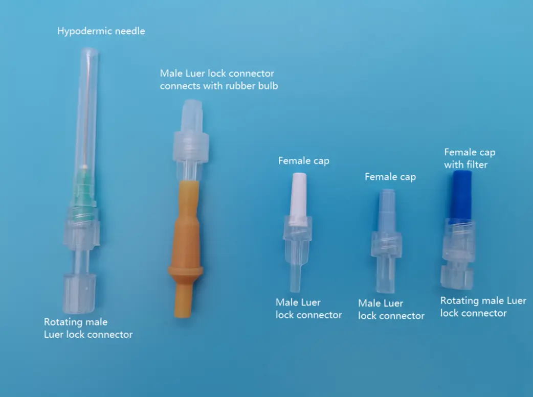
Threaded luer-lock versus slip connections
A threaded luer-lock connection provides a mechanical retention feature. When the mating components are compatible and fully engaged according to their instructions for use, the lock can reduce accidental separation compared with a simple friction-fit connection.
However, a luer lock is not automatically secure. Cross-threading, partial engagement, damaged threads, overtightening, incompatible tapers, stressed tubing, and repeated reconnection can compromise the joint. Users also need enough access and visibility to confirm engagement; a connection hidden under a dressing or caught against bedding is more difficult to inspect.
Slip connections rely primarily on friction. They may be appropriate only where the product system and intended use support them. They are generally more vulnerable to traction, pressure changes, rotational movement, and handling variability than a properly assembled locking connection.
Straight, angled, and branched connectors
Connector geometry affects both flow path and mechanical loading. A straight connector is simple and suitable for an in-line connection when the tubing route is also straight. If the tubing must turn sharply, however, a straight configuration can transfer bending force to the joint or create a kink near the catheter.
Angled connectors can reduce kinking and strain when a line needs to change direction. Their benefit depends on the actual routing, securement location, bend radius of the tubing, and available slack. An angled component that is unsupported can create a lever arm and increase pull-out force at the connection.
Y-connectors and multiport arrangements add branches, interfaces, dead spaces, and handling steps. They may be necessary for the therapy or drainage architecture, but each additional interface should have a clear purpose. More access points mean more opportunities for misconnections, contamination, unplanned opening, and overlooked inspection points.
Needleless connector designs
Needleless connectors permit needle-free access to vascular catheters. Their exterior septum is repeatedly touched, disinfected, connected, and disconnected, making it a critical barrier between the environment and the fluid pathway.
Common designs include split-septum connectors, which have a relatively direct fluid path and no internal mechanical valve, and mechanical-valve connectors, which use internal moving elements. Mechanical designs may be described by their displacement behavior: negative, positive, neutral, or anti-reflux.
Displacement refers to fluid movement associated with connection or disconnection and, depending on the design, other pressure changes. Negative displacement can contribute to blood reflux into the catheter at disconnection. Reflux may increase the likelihood of thrombus formation and occlusion. Positive or neutral displacement designs aim to manage that behavior differently, but the label alone does not establish lower infection risk or superior clinical performance in every setting.
Past FDA action requiring postmarket surveillance of certain positive-displacement needleless connectors is an important reminder. The agency had received safety information raising concerns about bloodstream infection risk, while also noting that available reports had important limitations and could not by themselves establish comparative causation. Connector complexity, cleaning practices, flushing procedures, patient populations, and local implementation can all affect outcomes.
For product developers and hospital evaluators, the practical conclusion is clear: assess the complete connector-and-workflow combination, rather than assuming one displacement category solves both reflux and infection concerns.
Design for secure attachment under real handling conditions
Bench performance should reflect how the connection is actually used. A connector can appear secure when new and unstressed yet fail after line movement, repeated access, cleaning, transport, or tubing rotation.
Key design and verification questions include:
- Does the connection fully seat with a clear, repeatable user action?
- Can users detect incomplete engagement by sight, feel, or a defined stop?
- Is the required torque or push force achievable with gloves and in restricted access conditions?
- Does the connection resist axial pull, torsion, bending, pressure pulses, and cyclic movement expected in use?
- Does tubing stiffness transfer force to the connector when the patient moves or the line is repositioned?
- Do securement devices support the line without obscuring the joint or preventing inspection?
- Can the user disconnect the intended interface without inadvertently loosening the catheter-side connection?
Connection security is a system property. The catheter hub, extension set, stopcock, connector, tubing material, clamps, fixation method, and line routing must be considered together. Testing a connector only with ideal reference fittings may miss performance changes caused by a real assembled device.
A useful engineering practice is to identify the weakest interface after aging, storage, transport, repeated access, and representative chemical exposure. If the product is intended for use with disinfectants, drugs, lipid emulsions, or cleaning agents, material compatibility should be demonstrated for the specified exposure conditions. Visual integrity alone is not enough; cracking, loss of retention, swelling, valve changes, and leakage may develop without being immediately obvious.
Control compatibility and prevent unintended combinations
Connector compatibility should never be assumed solely because two parts appear to fit. A seemingly successful fit can still create inadequate retention, leakage, damaged threads, restricted flow, excessive dead space, or an incorrect flow path.
For manufacturers, compatibility boundaries belong in the design inputs, verification plan, labeling, and risk file. This includes identifying authorized mating components, relevant connector standards, pressure limits, cleaning agents, and use environments. If a device is only validated as part of a specific set, that limitation should be clear.
For healthcare organizations, product conversion requires more than replacing one connector stock-keeping unit with another. The evaluation should review:
- The catheter, extension set, connector, stopcock, and administration-set interfaces.
- The flushing and clamping sequence specified for the selected connector.
- Maximum pressure and flow requirements for intended therapies.
- Disinfection supplies and required contact or drying time under the facility protocol.
- Staff training needs, including any difference in connection, disconnection, or priming technique.
- The effect on existing securement, dressing, and line-labeling practices.
Avoid unofficial adaptors used merely to make incompatible products join. Such workarounds can add connections, defeat intended safeguards, and make accountability for the assembled pathway unclear.
Make inspection and handling part of the safety control
A secure connector still needs routine observation. Inspection should be built into normal line access, handoff, transport, dressing changes, and troubleshooting rather than treated as a separate task that is easy to miss.
A practical inspection sequence is:
- Trace the line from patient to source or collection point before connecting, disconnecting, or changing components.
- Check engagement at each relevant joint for full seating, damaged threads, gaps, cracks, wetness, or displaced collars.
- Check the environment for tension from bed rails, clothing, pumps, restraints, transfers, or tubing caught under the patient.
- Confirm clamps and stopcocks are in the intended state before altering a connection.
- Disinfect the access surface using the facility protocol and the connector manufacturer’s instructions before every access.
- Protect the connection after use so caps, covers, and tubing do not drag across contaminated surfaces or become unsecured.
A disinfection process must be practical enough to be performed consistently. Connector geometry matters here: recessed surfaces, narrow crevices, complex valve housings, and difficult-to-reach septa can increase the challenge of cleaning. Product developers should include representative disinfection steps in usability work, not merely chemical compatibility testing.
Reduce traction and displacement at the patient interface
Many separations originate away from the connector itself. A line becomes taut, tubing is pulled during repositioning, an infusion pump moves, or an extension set twists. The force then reaches the hub or stopcock.
Use routing and securement to keep the connection neutral rather than under continuous pull. Provide enough slack for expected movement, but not so much that loops snag on equipment. Place securement so it supports the tubing close enough to reduce leverage without blocking access to the connection or hiding a leak.
For drainage systems, routing and height management are especially important. A disconnected patient line can produce a different and potentially dangerous outcome than a disconnected infusion line. The system design should support rapid recognition of separation, clear identification of stopcock positions, and controlled response procedures established by the clinical team and device instructions.
Use postmarket data to find weak links early
Complaint handling should distinguish among leakage, accidental disconnection, cracked housings, difficult assembly, occlusion, contamination concern, and user confusion. Combining these events into a single “connector failure” category hides patterns that may point to different corrective actions.
Investigations should retain, when possible, the complete affected assembly rather than only the detached connector. Record lot information, mating components, line configuration, dwell time, therapy or drainage context, securement method, visible damage, and whether the joint was found fully engaged. Photographs taken under established incident procedures can help identify recurring interface or routing patterns.
Trend data should be reviewed by connector type, unit or care setting, catheter type, staff workflow, and time since product introduction. A rise in events after a product conversion may indicate a training, compatibility, or workflow issue—not necessarily a material defect. Conversely, repeated events with the same lot, component interface, or failure appearance may require supplier investigation, design review, field action, or regulatory reporting under applicable requirements.
A focused prevention checklist
Catheter connector disconnection prevention is strongest when the following controls are aligned:
- Select connector architecture for the therapy or drainage hazard, not for convenience alone.
- Use validated, compatible components and avoid unnecessary adaptors.
- Verify secure attachment and resistance to realistic pull, torsion, pressure, and aging conditions.
- Account for displacement and reflux behavior in the specified flushing and clamping workflow.
- Choose designs that can be accessed and disinfected reliably in real clinical conditions.
- Route and secure tubing to reduce tension, twisting, snagging, and lever forces.
- Make connection inspection part of every handling event.
- Capture detailed postmarket data so recurring failure modes can be identified and corrected.
The connector should be treated as a controlled interface, not a passive accessory. When connection integrity, hygiene, compatibility, and workflow are designed and monitored together, the same small component is less likely to become the starting point for a preventable leak, separation, contamination event, or harmful change in fluid flow.