Medical Devices, Materials, Design & Development, Quality & Testing
CT Detector Design Tradeoffs: Balancing Resolution, Noise, Dose, and Scan Coverage
Updated
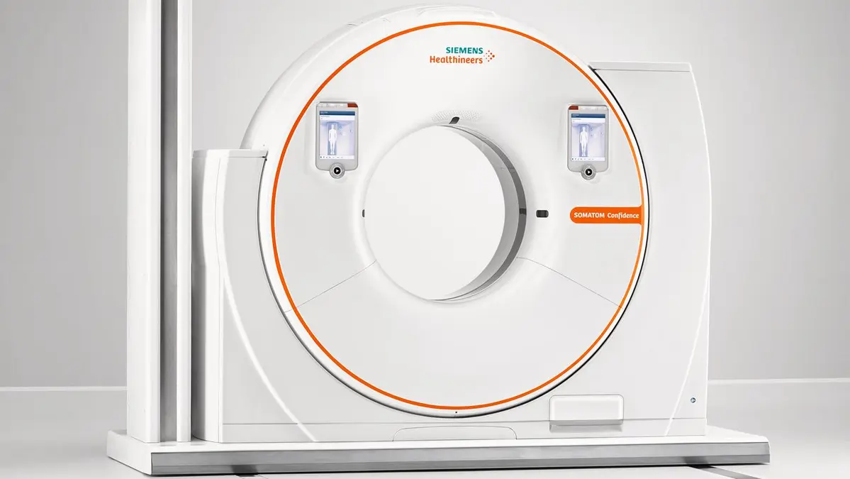
CT detector design sets practical limits on what a scanner can resolve, how quickly it can cover anatomy, and how efficiently it uses X-rays that have passed through the patient. The apparent choices are simple: use smaller detector elements for more detail, add rows for more coverage, or use more advanced detector materials for better signal capture. In practice, each choice changes noise, dose efficiency, calibration burden, artifact behavior, and reconstruction demands.
For equipment developers, physicists, and CT users, the key point is that no detector geometry is universally better. The suitable design depends on the clinical task: fine bone detail, low-contrast abdominal imaging, cardiac motion control, whole-organ perfusion, or rapid trauma coverage all place different demands on the detector.
The detector’s role in CT image quality
A conventional energy-integrating CT detector usually converts X-rays to visible light in a scintillator, then converts that light to an electrical signal with a photodiode. The detector must measure a very wide range of transmitted X-ray intensities. A ray passing through the shoulders or pelvis may deliver far fewer photons than a ray passing through the lungs, yet both measurements must remain accurate enough for reconstruction.
Detector performance affects more than a single image-quality number. Important characteristics include:
- Spatial sampling: how finely the system measures the X-ray beam across the patient and along the patient axis.
- Quantum efficiency: how effectively incident X-rays are absorbed and converted into usable signal.
- Geometric efficiency: how much of the detector face is active area rather than septa, housing, or other inactive gaps.
- Electronic noise and dynamic range: whether small signals can be measured without being buried in electronics noise, while large signals avoid saturation.
- Uniformity and stability: whether channels respond consistently over a rotation and between calibrations.
- Temporal response: whether the detector signal ends quickly enough to avoid carryover into later views.
- Cross-talk: unwanted signal transfer between neighboring channels, either optically, electrically, or through scattered radiation.
A scanner can partly compensate for detector limitations through calibration and reconstruction, but those corrections cannot recover photons that were never detected. Detector efficiency therefore has a direct relationship with dose efficiency, especially for low-contrast tasks where quantum noise is the main limitation.
Smaller detector elements: more detail, fewer photons per channel
Detector element size influences resolution in two directions. In the image plane, smaller channels improve sampling of the attenuated X-ray fan. Along the patient’s length, smaller detector rows support thinner acquired sections and better z-axis resolution.
Fine detector sampling is useful for high-contrast structures such as cortical bone, calcifications, lung detail, small airways, and vascular boundaries. Thin acquisitions also support near-isotropic voxels, making multiplanar reformats and 3D renderings more reliable. A structure that is sharply represented in axial images is less likely to appear blurred when reformatted coronally or sagittally.
The penalty is photon statistics. A smaller element receives fewer X-ray photons for a given exposure. X-ray quantum noise is statistical, so reducing detected photon counts increases uncertainty in the measured signal. This can reduce low-contrast detectability even when small, high-contrast structures look sharper.
Thin reconstructed slices create a related problem. A thin slice includes less data than a thicker slice reconstructed from the same scan, so it is noisier. Operators may respond by increasing tube output to restore familiar noise levels. That can turn a resolution-driven protocol decision into a dose increase.
This does not mean fine detectors always require higher dose. Thin data can be acquired once and reconstructed at several thicknesses. For example, a protocol may retain thin images for vascular or orthopedic review while creating thicker, lower-noise reconstructions for soft-tissue interpretation. The dose decision should be based on the diagnostic task, not on a desire to make every reconstructed series as thin as possible.
Resolution is not determined by detector width alone
Detector size is only one limit in the imaging chain. The effective resolution also depends on focal spot size, source-to-detector geometry, projection sampling, patient motion, image matrix, reconstruction field of view, and reconstruction kernel.
A sharp reconstruction kernel can preserve higher spatial frequencies, making edges and fine structures more visible. It also changes the image noise texture and usually increases visible noise. Conversely, a smooth kernel reduces noise at the cost of edge detail. A small detector element cannot fully offset an overly large reconstruction field of view, a motion-limited acquisition, or a soft kernel selected for a high-resolution task.
Single-row, multi-row, and wide detectors compared
The main distinction between detector configurations is coverage in the z-axis: the direction along the patient table.
| Detector configuration | Data collected per rotation | Main advantages | Main tradeoffs |
|---|---|---|---|
| Single-row | One detector row or one acquired section | Simpler geometry and calibration; limited cone-beam effects | Slow volume coverage; less practical for modern volumetric and fast helical work |
| Multi-row | Multiple narrow rows | Faster scanning, thin sections, flexible reconstruction thickness, improved 3D imaging | More channels, septa, calibration complexity, and potential z-axis efficiency losses |
| Wide detector | Many rows providing broad z-axis coverage in one rotation | Large anatomical volume per rotation; useful for cardiac, brain, and dynamic examinations | Cone-beam reconstruction challenges, scatter management, cost, heat and data-rate demands |
Single-row detectors
Single-row CT collects one section at a time. Its limited coverage makes it comparatively slow for long scan ranges and less flexible for thin-section volumetric imaging. However, the geometry is relatively simple: the X-ray beam is narrow in the z-axis, and cone-beam effects are less demanding than with broad detector arrays.
In current practice, the main value of single-row concepts is as a baseline for understanding why multidetector systems changed CT. They illustrate the fundamental tradeoff between narrow collimation and scanning speed. Narrow beams can provide thin sections, but covering a long anatomy requires more table travel and more time.
Multi-row detectors
Multi-row detector CT divides the detector in the z-axis into multiple elements. Several sections can be acquired during each gantry rotation, allowing much faster coverage than single-row systems.
This architecture supports thin-section acquisitions without making a chest, abdomen, or vascular examination impractically long. It also lets systems combine detector rows for thicker acquisitions when the task favors lower noise over maximum z-axis detail.
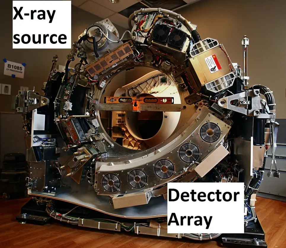
The design cost is not only additional detector channels. Separations between rows create inactive areas. Detector septa are necessary to limit optical and electrical cross-talk, but they reduce geometric efficiency because some transmitted X-rays hit non-sensitive material. In addition, the edges of the X-ray beam are not perfectly sharp. The penumbra at the beam edges may expose tissue without contributing fully usable image data.
The net dose efficiency of a multi-row system depends on the full geometry, including collimation, focal spot, detector design, selected configuration, and scan range. It should not be judged simply by the number of detector rows.
Wide detectors
Wide-area detector systems extend z-axis coverage substantially. They can capture an entire organ or a major portion of it in one rotation, reducing the need for table movement during the critical acquisition. This is valuable when timing matters, such as imaging a moving heart, evaluating brain perfusion, or capturing a contrast bolus across a defined volume.
Wide coverage can reduce motion artifacts and shorten breath-holds. It can also avoid helical stitching across an organ when a single rotation covers the required anatomy. But a wider detector does not automatically mean lower patient dose.
A broad beam creates a more pronounced cone-beam geometry. Rays at the outer detector rows diverge more strongly from the central plane, and reconstruction must accurately account for the three-dimensional acquisition. Wide coverage can also increase scatter reaching the detector, affecting contrast and requiring appropriate correction methods.
Protocol design matters especially at the beginning and end of a helical scan. The scanner may need to acquire data outside the planned image range to reconstruct the first and last images. This extra irradiated length is often called over-ranging or overranging. Beam collimation and adaptive shutters can reduce unnecessary exposure, but the actual dose impact depends on the scanner design and chosen protocol.
Geometric efficiency: why detector gaps matter
Geometric efficiency describes the fraction of transmitted X-rays that reach active detector material. It is distinct from absorption efficiency, which describes how effectively the active material absorbs the X-rays that reach it.
Smaller detector elements generally require more boundaries, septa, and readout structures over a fixed physical area. If those inactive regions become a larger share of the detector face, fewer useful photons are measured. This is one reason fine sampling cannot be treated as a free resolution upgrade.
Manufacturers manage this tradeoff through tightly packed arrays, reflective separators, optical isolation, collimator design, and detector electronics. The goal is to preserve channel separation while minimizing dead area. The design target is not simply the smallest possible element; it is the smallest element that delivers sufficient resolution, stable response, acceptable cross-talk, and adequate dose efficiency for the intended applications.
Detector materials and temporal performance
Most conventional CT systems use solid-state scintillator detectors. The scintillator should absorb X-rays efficiently, produce a strong and stable light signal, and stop emitting quickly when the exposure changes.
Afterglow and fast scanning
Afterglow is residual light emission from a scintillator after X-ray exposure ends. In CT, detector readings are made rapidly as the gantry rotates. If light from one view persists into the next, the signal can be blurred in time. This may contribute to artifacts or reduce accuracy in fast acquisitions.
Low afterglow is particularly important for high-speed rotation, moving anatomy, and applications where rapid changes in attenuation or contrast enhancement must be represented accurately. Material selection must balance afterglow against light output, X-ray stopping power, manufacturability, uniformity, and long-term stability.
Dynamic range and channel consistency
CT detectors need a large dynamic range because attenuation varies greatly across patient size, anatomy, and projection angle. A detector channel must retain sensitivity when few photons reach it and avoid saturation when transmission is high.
Channel-to-channel consistency is equally important. A small response mismatch can appear as rings, bands, or other structured artifacts after reconstruction. Detector calibration corrects known variations, but stability determines how often recalibration is needed and how well correction holds during clinical use.
Temperature changes, electronics drift, aging, and material behavior can all affect response. For this reason, detector development includes both initial performance measurement and stability testing over operating conditions and expected service life.
Where photon-counting detectors change the tradeoff
Photon-counting CT detectors use a direct-conversion semiconductor approach rather than measuring the total integrated energy deposited in a scintillator over an exposure interval. In principle, they can count individual X-ray photons and sort them into energy thresholds or bins.
This architecture can support smaller detector pixels and spectral information, but it introduces its own engineering limits. At high photon flux, the electronics must process events quickly enough to avoid pulse pileup and count losses. Semiconductor material quality, charge transport, polarization behavior, pixel cross-talk, and threshold stability are central design concerns.
Photon-counting systems therefore do not remove the familiar resolution-noise-dose relationship. Small pixels still receive fewer photons, and clinical value still depends on task-specific reconstruction and dose management. Their potential benefit comes from using detected photons and spectral information more effectively, not from bypassing photon statistics.
Practical decisions for protocol and system design
The most useful question is not, “What detector has the highest resolution?” It is, “What detector configuration provides enough task-specific image quality with the least unnecessary exposure and complexity?”
For system specification and protocol review, assess these points:
- Define the diagnostic task. High-contrast bone imaging, low-contrast liver lesion detection, coronary CT angiography, and dynamic brain imaging require different balances of resolution, noise, and coverage.
- Separate acquired thickness from displayed thickness. Retain thin raw data when needed, but reconstruct thicker series for low-contrast interpretation where appropriate.
- Check coverage against motion and timing. Wide detectors can reduce motion and improve temporal coordination, but only where the covered volume and reconstruction geometry suit the examination.
- Evaluate dose efficiency, not just nominal collimation. Consider active detector fraction, beam penumbra, over-ranging controls, automatic exposure control behavior, and reconstruction options.
- Review artifact performance under realistic conditions. Test uniformity, ring artifacts, temporal response, high-attenuation objects, off-center positioning, and large-patient conditions.
- Treat reconstruction as part of detector performance. Iterative and other advanced reconstruction methods may permit lower-noise images at a given exposure, but protocol validation must confirm that relevant low-contrast and high-contrast tasks remain adequately represented.
CT detector design is a system-level compromise. Smaller elements improve sampling but challenge photon economy. More rows improve speed and z-axis coverage but add geometry, scatter, and calibration demands. Wider detectors can capture anatomy in fewer rotations but require careful management of cone-beam effects and scan range. The effective design is the one that matches detector geometry, material response, acquisition settings, and reconstruction to the clinical question rather than maximizing any one specification.