Materials, Manufacturing, Quality & Testing
Troubleshooting LSR Injection Molding Defects
Updated
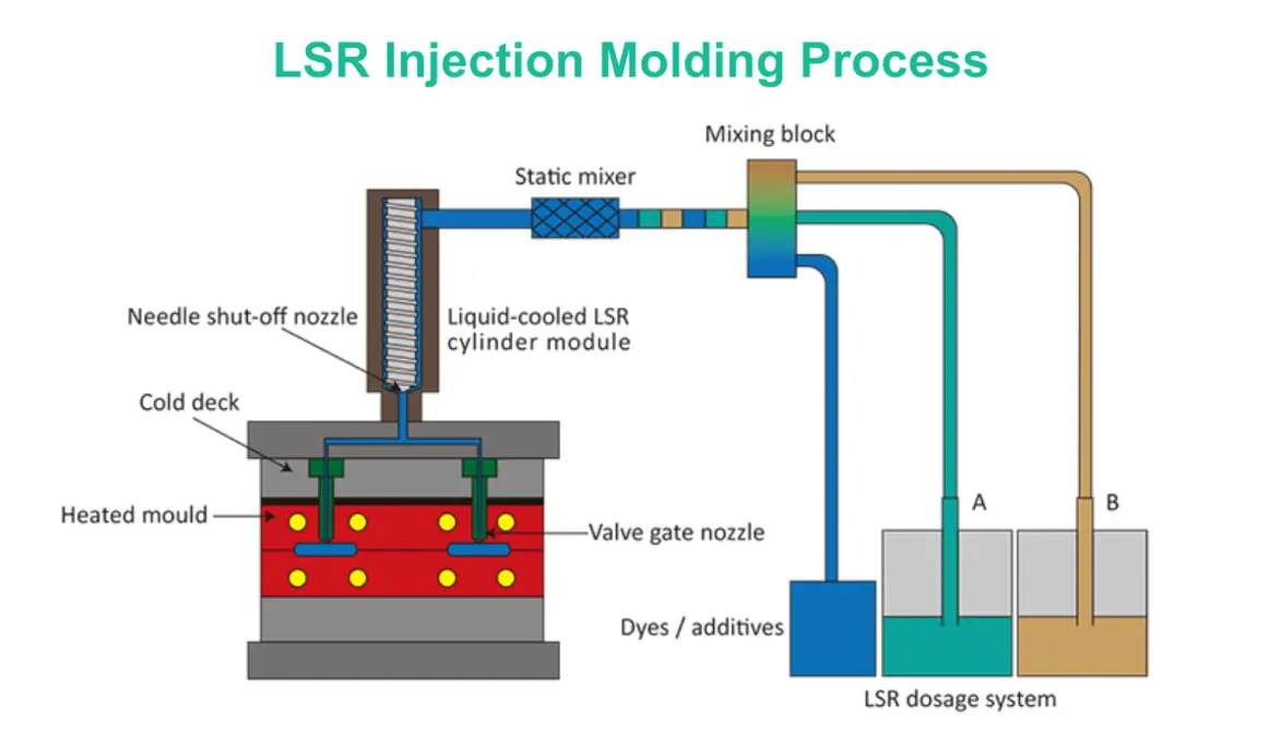
LSR injection molding defects are rarely corrected by changing one pressure or temperature setting. Liquid silicone rubber is low viscosity before cure, so it can enter very small clearances, carry air through a cavity quickly, and react strongly to changes in mold temperature, metering accuracy and vent condition.
A practical troubleshooting method starts with the defect pattern. Record the cavity number, defect location, part weight, material batch, process settings and recent changes before making adjustments. Then separate likely causes into four areas: material delivery, mold flow and venting, machine performance, and cure conditions. Change one verified variable at a time and compare the result with approved parts.
Start with the defect pattern
The location and consistency of a defect narrow the investigation quickly.
- One cavity only: Inspect the local gate, runner branch, vent, cavity temperature, insert fit and mold surface.
- Several cavities in a repeatable pattern: Look for runner imbalance, uneven mold heating, cold-runner restrictions or clamping and alignment issues.
- All cavities: Check shot volume, A/B metering ratio, material supply, injection profile, vacuum performance and overall mold temperature.
- Random shot-to-shot variation: Prioritize material delivery, air entering the meter-mix system, check-valve performance, temperature control and process repeatability.
Part weight is a useful early check. Stable weight with a defect repeatedly in the same location usually points toward tooling, venting or local thermal conditions. Variable weight suggests that shot delivery or material metering needs attention before mold changes are made.
For medical components, retain the defect investigation as part of the production record. A visual improvement alone is not enough if a parameter change can affect dimensions, hardness, tensile properties, sealing performance, extractables controls or validated process limits.
Short shots and inconsistent filling
A short shot is an incomplete cavity fill. It may appear as a missing feature, thin edge, incomplete membrane, underweight part or uneven surface at the last-fill location. In multi-cavity molds, one or more cavities may be short while others are acceptable.
Check the flow path before raising pressure
Increasing injection pressure can sometimes fill the cavity, but it can also force flash at a weak shutoff or compress trapped air into a visible defect. Work through the flow path first:
- Confirm material supply and metering. Verify that both LSR components are available, correctly connected and delivered at the specified ratio. Look for air leaks, cavitation, blocked filters, damaged seals, inconsistent pump output and material near or beyond its supplier-defined handling life.
- Inspect the static mixer, nozzle and cold runner. Partially cured LSR or contamination can restrict flow. A restriction near the nozzle or gate can cause a cavity to fill slowly or unevenly.
- Compare cavities. A cavity-specific short shot points to its gate, runner branch, vent or local heater zone. If all cavities are short, investigate shot size, injection speed, pressure limits and a global restriction.
- Inspect the last-fill area. If air cannot leave the cavity, the flow front may stop before the feature is filled. Clean and inspect vents rather than assuming more pressure is the answer.
- Review mold temperature. Excessive local heat can begin curing material too early near a gate or thin flow path. Uneven temperature can make one region fill differently from another.
After these checks, use controlled changes to injection speed, pressure or shot volume. A staged injection profile may be more useful than a broad increase in speed: a fast enough initial fill may prevent premature cure, while a controlled final fill can give air time to reach the vents.
Air entrapment, bubbles and blisters
Air-related defects may be visible as internal bubbles, surface blisters, whitening, burns or voids. They commonly appear at the last-fill area, around inserts, at abrupt transitions, in thick sections and where multiple flow fronts meet.
Distinguish cavity air from air in the material
Air can enter from two different places, and the correction is different.
Cavity air is displaced as LSR enters the mold. It needs a defined route through vents, a vacuum system where used, or both. Blocked vents, worn parting surfaces, poor vacuum seals and insufficient evacuation time can leave air trapped in the cavity.
Material-borne air enters through supply connections, leaking seals, meter-mix equipment, poor system priming or cavitation. If bubbles occur across many cavities and do not correspond to a last-fill location, inspect the material delivery system closely.
Start by checking vacuum lines, seals, gaskets, vent surfaces and vacuum timing. Verify that vents are clean and not blocked by cured silicone, mold-release residue or debris. The vent must release air without creating a path for unacceptable flash, so vent condition and vent geometry must be evaluated together.
Injection speed also matters. A fast flow front can trap air before it reaches a vent. However, reducing speed across the entire fill can create a new problem if curing begins before the cavity is complete. Make small, documented changes to the relevant portion of the injection profile and inspect the defect location after each trial.
If the defect is concentrated around an insert, check insert location, fit, surface condition and preheat practice where applicable. Cold or poorly seated inserts can alter local flow and cure behavior.
Flash, backrind and excessive trimming
Flash is a thin film of cured silicone escaping through a parting line, vent, insert interface, ejector location or other shutoff surface. Because uncured LSR flows readily, a small clearance can produce significant trimming work.
The most useful question is: where is the flash occurring?
| Flash location | Likely causes to check | First corrective direction |
|---|---|---|
| Parting line | Contamination, damaged or worn shutoff, poor alignment, excessive fill | Clean and inspect mating surfaces; verify shot repeatability |
| Vent area | Overfilling, excessive injection pressure, vent damage or oversize vent | Confirm fill level and vent condition before reducing venting capability |
| Around an insert | Insert tolerance, seating, movement or worn interface | Inspect insert and shutoff fit; do not rely on process changes alone |
| Ejector or moving feature | Wear, damage, poor alignment or incomplete closure | Inspect mechanical condition and mold movement |
Check part weight before changing clamp force or injection pressure. If weight varies, correct metering or delivery instability first. If weight is stable and flash remains in one location, the mold usually needs focused inspection.
Reducing shot size, injection pressure or final-fill speed may reduce flash when the cavity is being overfilled. But repeated flash at a single parting-line area is often a tooling issue, not a sustainable process-setting issue. Mold alignment, plate parallelism, insert condition and contamination should be addressed through the approved maintenance process.
Do not respond to flash by simply eliminating venting. A mold that is sealed too aggressively may replace flash with air traps, short shots or poor surface finish.
Surface defects: flow lines, roughness and discoloration
Visible flow lines, streaks, orange-peel texture, dull patches or localized discoloration can result from a combination of flow, mold surface, temperature and contamination conditions.
Begin by mapping the mark to the flow path. A defect that begins near the gate may indicate high shear, a restricted nozzle opening, a cold-runner issue or premature cure at the injection path. Marks near flow-front meeting points may indicate poor venting, uneven fill or a temperature difference between flow paths.
Check these items in order:
- Gate and runner condition, including restrictions or partially cured deposits.
- Nozzle and shutoff function, especially whether the opening restricts flow.
- Mold surface cleanliness and the controlled use of any mold-release product.
- Mold temperature consistency across zones and cavities.
- Injection speed profile and local pressure demand.
- Material identity, viscosity range and storage condition.
A material grade change should not be the first reaction to surface marks. First show that the existing approved grade is being delivered, mixed, filled and cured within its intended process window. If a different viscosity, hardness or pigment system is being considered, assess its impact on device requirements and revalidate as required by the quality system.
Tacky surfaces, soft parts and incomplete cure
A tacky surface, low hardness, sticking during demolding or variable cure can indicate incomplete crosslinking. Treat this as a material, mixing and thermal-control investigation rather than only a request for more mold heat.
First confirm the material identity and the intended A/B ratio. Check pump output, check valves, supply hoses, mixer condition and whether the system was correctly purged after a material change. A partially blocked or partially cured static mixer can affect both flow and mix quality.
Then investigate contamination. Addition-cure silicone systems can be inhibited by contact with certain materials or residues. Potential sources include unsuitable cleaning agents, adhesive residues, sulfur-containing compounds, some rubbers, amines, tin-containing materials and residues from maintenance activities. Do not assume that a cleaner, tape, glove, insert coating or release agent is compatible; control and qualify materials that contact uncured LSR.
Next, verify actual mold temperature rather than relying only on the controller display. Inspect heaters, thermocouples, temperature zones and thermal contact. A cold zone, poor heat transfer near an insert or an unheated local feature can leave part of the component undercured even when the average setting appears correct.
Increase cure time or temperature only through a controlled process adjustment. Excessive cure conditions can affect cycle time, demolding behavior and part properties. For regulated products, evaluate any change against the validated process and the defined acceptance criteria.
Premature cure and restricted flow
Premature curing in the nozzle, static mixer, sprue or cold runner causes unstable filling, rising injection pressure and eventually short shots. It may also create surface defects from degraded or partially cured material entering the cavity.
Inspect the transition between the cold material delivery path and the heated mold. Confirm that cooling where required is functioning and that there is no unexpected heat transfer into the runner or nozzle region. Review dwell time: material held too long in a warm zone is more likely to begin curing.
Remove cured deposits using approved maintenance methods. Avoid using improvised solvents or tools that could damage surfaces, leave residues or introduce cure inhibition. After maintenance, document the condition and confirm a stable restart using defined inspection samples.
Build a repeatable troubleshooting routine
A useful LSR defect log should include:
- Date, machine, mold and cavity number
- Material lot, component ratio and supply setup
- Part weight and defect photographs where permitted
- Defect location relative to gate, vents, inserts and last-fill area
- Mold and runner temperature settings, plus measured values when available
- Injection profile, shot volume, pressure and vacuum conditions
- Maintenance, cleaning or tooling changes made before the defect appeared
- One change made, the sample size reviewed and the result
Avoid changing pressure, speed, temperature and clamp settings all at once. That approach may produce acceptable parts briefly but leaves the underlying cause unknown. A stable LSR molding process depends on controlled material delivery, clean and functional venting, balanced flow, sound shutoffs and uniform curing conditions.
When a defect persists after basic checks, stop making broad parameter changes. Escalate to qualified process, tooling or equipment personnel for inspection of the mold, meter-mix system and validated process window. This is particularly important when defects could affect a medical device’s fit, seal, mechanical performance or patient-contacting material controls.