Materials, Design & Development, Quality & Testing, Medical Devices
Radiopaque Marker Materials and Placement: Balancing Visibility, Flexibility, and Device Safety
Updated
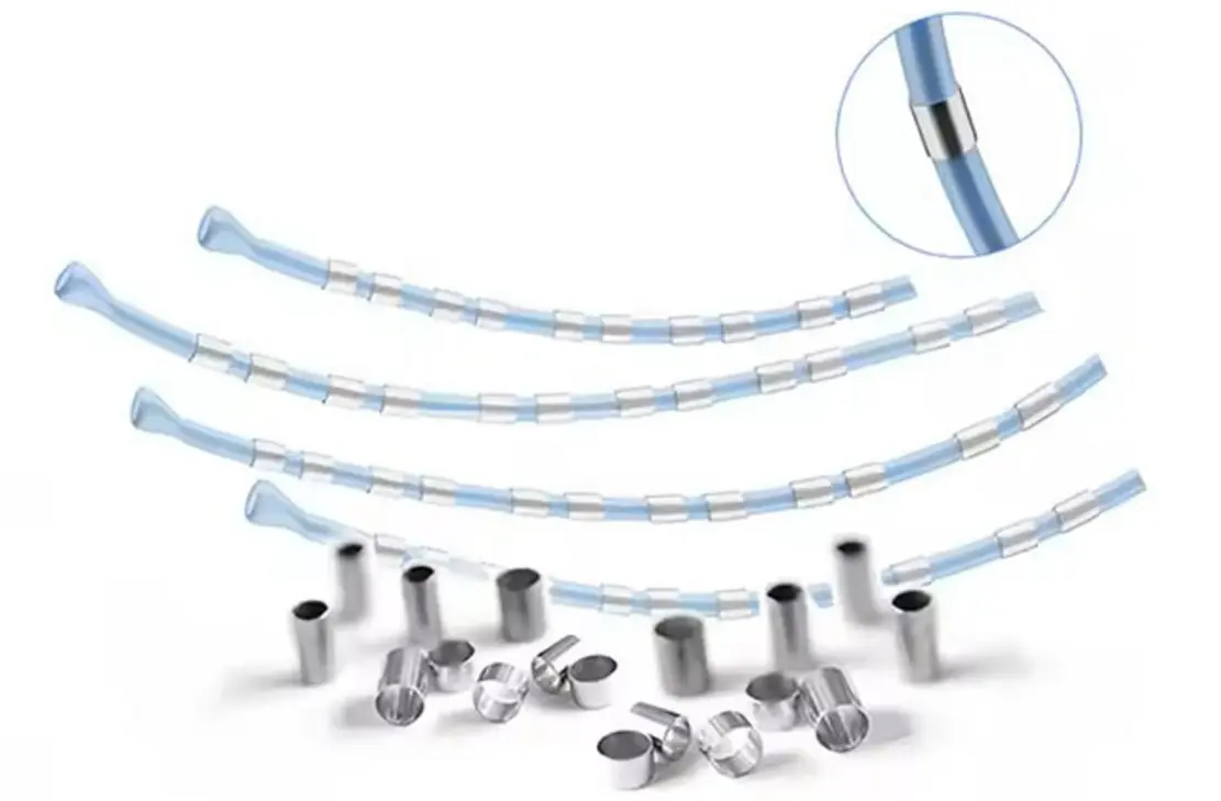
Radiopaque markers give clinicians fixed reference points under fluoroscopy or X-ray. They may look like minor components, but their material, dimensions, fixation method, and position can change a device’s trackability, flexibility, safety profile, and manufacturing yield.
For radiopaque marker materials and placement in medical devices, the target is not maximum X-ray visibility in isolation. The practical target is repeatable visibility at the clinically meaningful feature, with no unacceptable effect on device function or risk of marker movement, fracture, or detachment.
Start with the clinical question the marker must answer
A marker should communicate a specific feature or state during use. Before choosing a metal or specifying a band size, define what the operator needs to see.
Typical questions include:
- Where is the distal tip?
- Where are the working ends of a balloon?
- Has a stent reached its intended landing zone?
- Where are the proximal and distal ends of an implant after deployment?
- Is a guidewire tip approaching, crossing, or extending beyond a target?
- Has a tissue marker remained at the intended anatomical location?
This definition drives placement. A visible marker that is not aligned with the clinically relevant feature can create false confidence. For example, a distal catheter marker may show where the shaft ends but not where a balloon shoulder, stent edge, or treatment zone begins.
Marker design should therefore be linked to the device’s use scenario, imaging conditions, anatomical location, and delivery method. Do not simply copy the marker layout of a superficially similar device.
Compare the common radiopaque marker materials
High-density metals attenuate X-rays more strongly than many catheter polymers and structural alloys. Platinum-based materials, tantalum, and gold are established options for small markers. Tungsten is also used, either as a metal component or as filler in polymer formulations.
Material selection is only one part of visibility. Marker cross-section, wall thickness, length, surrounding materials, overlap with other device components, imaging angle, X-ray settings, and anatomy all affect the image seen by the user.
| Material or approach | Useful characteristics | Design limitations to assess | Common design roles |
|---|---|---|---|
| Platinum-iridium | High radiopacity, strong corrosion resistance, good durability, available as precision tubing and bands | High material cost; a discrete metal band can create a local stiffness increase | Catheter bands, guidewire markers, implant markers, neurovascular and vascular devices |
| Tantalum | High radiopacity, corrosion resistance, established implant use, ductile material behavior | Form factor and attachment method must suit the application; thin features may be vulnerable to damage during processing | Marker bands, stent markers, coils, implant reference markers |
| Gold | High radiopacity and good corrosion resistance; soft and readily formed | Low mechanical strength relative to harder alternatives; deformation or wear must be considered | Small markers where high visibility is needed and loading is limited |
| Tungsten | High density and strong radiopacity; available in metal and filled-polymer options | High stiffness in metallic forms; particle-filled polymers require dispersion, retention, and process control | Disposable device markers, radiopaque polymer sections, selected structural components |
| Radiopaque polymer compound | Can distribute visibility through a soft or flexible section rather than a discrete metal ring | Usually needs more material volume than a dense metal marker; filler can alter extrusion, bonding, toughness, and surface quality | Catheter tips, molded components, soft shafts, strain-relief sections |
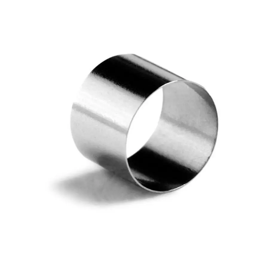
Platinum-iridium is commonly specified for small, durable marker bands because it combines strong fluoroscopic visibility with corrosion resistance and workable mechanical properties. The alloy composition, dimensions, and temper still matter. “Platinum-iridium” is not a complete design specification.
Tantalum is another frequent choice. It provides strong contrast and is used in marker bands and implantable marker features. For stents and other implants, a tantalum marker can make the implant ends or other critical locations easier to identify without requiring the whole structure to be made from a highly radiopaque material.
Gold can be appropriate where a soft, highly radiopaque material is useful, but softness is a real engineering constraint rather than a minor purchasing detail. The marker can deform during crimping, swaging, stent compression, or repeated flexing if geometry and process controls are not suitable.
Visibility is a system property, not a material ranking
Design teams sometimes treat radiopacity as a simple comparison between metals. In practice, the visible result comes from the entire device and imaging environment.
A short, thin band of a dense material may be less useful than a slightly longer feature with a clear profile. Two markers may also merge into one image if their spacing is too small at the expected magnification or projection angle. Conversely, a larger marker can obscure neighboring features or make it difficult to distinguish the true edge of a balloon or implant.
Define measurable visibility requirements early. These may include:
- Ability to identify the marker at the intended working distance.
- Ability to distinguish paired markers from one another.
- Contrast relative to relevant anatomy, contrast media, and adjacent device parts.
- Visibility at expected projection angles.
- Consistency across the imaging systems and settings relevant to the intended procedure.
Bench fluoroscopy assessment should use representative assemblies rather than loose markers on a fixture. A marker’s appearance can change when it is covered by polymer, placed over a braid or coil, positioned beside a balloon, or viewed through other radiopaque components.
Place markers at functional boundaries
Marker placement should show the feature that controls clinical action. Common patterns are straightforward, but each has specific trade-offs.
Catheters and balloon catheters
A distal-tip marker helps users locate the device endpoint. Balloon catheters often use markers near the balloon shoulders to show the inflatable working length and support accurate treatment-zone alignment.
The marker should not be placed so close to a bond line that it concentrates stress, interferes with adhesive coverage, or reduces the effective bonded area. It also should not distort the shaft or balloon transition enough to alter crossing profile, trackability, or deflation performance.
For small-diameter catheters, a marker band can be one of the stiffest features near the distal section. A local stiffness discontinuity may reduce navigability or become a fatigue concern during tortuous-path use. Options to investigate include reducing band length or wall thickness, moving the band slightly, using a radiopaque polymer section, or adjusting the stiffness transition of the surrounding shaft.
Guidewires
Guidewire markers may identify the distal tip, a shaping zone, or a working-length reference. They must be considered together with the core wire, distal coil, welds, polymer jacket, and any hydrophilic coating.
The distal region is repeatedly bent, torqued, and loaded during navigation. A marker that is secure in a static pull test may still be vulnerable to cyclic bending, coil interaction, or surface damage. Avoid introducing sharp edges, abrupt diameter changes, or poorly supported transitions that can snag, wear a polymer jacket, or create a stress riser.
Stents and other implants
Markers commonly identify proximal and distal implant ends because those positions matter during deployment and follow-up imaging. Marker location must remain meaningful after crimping, expansion, foreshortening, and any intended shape change.
For self-expanding or balloon-expandable structures, assess the marker with the entire crimp-and-deploy sequence. A marker can shift, fracture, or alter local strut deformation even when the unconstrained implant appears satisfactory. Attachment points must not compromise structural fatigue performance or create an unacceptable profile increase.
Tissue and surgical markers
Implantable tissue markers must remain where they are placed. Visibility alone is insufficient if the marker can detach, migrate, fragment, or rotate away from the intended reference location.
A smooth metal bead, ring, rod, or suture-like feature may require a secondary fixation approach, depending on the tissue, implantation technique, expected loading, and duration of use. The fixation design should be evaluated as part of the marker system. A strong marker material does not guarantee secure retention in tissue.
Control the flexibility penalty of metal marker bands
A marker band changes local bending behavior because it adds material with different stiffness and geometry from the shaft beneath it. The concern is not simply that metal is stiff. The concern is the abrupt change in bending stiffness across the marker boundaries.
Useful design controls include:
- Keep the marker only as long and thick as needed for the visibility requirement.
- Avoid stacking multiple bands in the most flexible distal region unless their spacing and combined stiffness have been evaluated.
- Use a gradual shaft stiffness transition before and after the marker location.
- Evaluate whether a filled polymer marker or a thinner metallic feature can meet the imaging need.
- Maintain smooth outside-diameter transitions under any protective polymer layer.
- Consider the effect of the marker on torque response, pushability, kink resistance, and withdrawal force, not only three-point bend results.
A marker can also affect the internal lumen. A band placed over a thin-wall shaft may constrict the shaft during assembly, especially when heat-shrink processing or bonding is involved. This can reduce guidewire clearance, fluid flow, or balloon inflation and deflation performance.
Design fixation against detachment and breakage
Marker safety depends heavily on retention. The relevant failure mode differs by device: a catheter band may slide or delaminate; an implant marker may crack during expansion; a tissue marker may pull free; and a wire marker may fatigue after repeated bending.
The attachment approach may include mechanical capture, swaging, crimping, welding, overmolding, adhesive bonding, polymer encapsulation, or integration into the device structure. Each has different risks.
Mechanical retention can provide robust positioning but may damage a thin substrate or create a sharp transition. Adhesive bonding can preserve a smooth profile but requires control of surface preparation, adhesive coverage, cure, sterilization effects, and aging. Polymer encapsulation can improve retention and surface smoothness, but the encapsulating layer must remain intact during flexing, abrasion, and insertion through accessories.
For implantable devices, assess any dissimilar-metal interfaces and manufacturing residues as part of the material compatibility and corrosion risk evaluation. Do not assume that two materials are acceptable together solely because each has a history of individual medical use.
Build verification around realistic use conditions
Marker verification should connect directly to the design risks. A dimensional check and static pull test are rarely enough.
A practical test plan may include the following areas:
Dimensional and visual inspection
Verify marker length, wall thickness, inside and outside diameter, axial position, spacing, concentricity where relevant, surface condition, and edge quality. Include inspection after final assembly, not only at incoming component inspection.
Imaging performance
Evaluate marker visibility in representative device configurations under relevant fluoroscopic conditions. Confirm that paired markers, implant ends, and working zones can be distinguished and that the marker does not mask another clinically important feature.
Mechanical retention and durability
Test the loads that can cause marker movement or damage: tensile loading, torsion, repeated bending, compression, push-pull cycling, accessory passage, balloon inflation, crimping, deployment, and withdrawal. The selected sequence should reflect the device’s actual use and worst-case handling.
Environmental and process effects
Assess marker integrity after sterilization, shelf aging, packaging distribution simulation where appropriate, and exposure to relevant fluids or temperature conditions. For polymer-filled radiopaque sections, include checks for filler-related changes in extrusion consistency, surface defects, mechanical properties, and bonding performance.
Usability review
Use the final marker layout in simulated procedure workflows. The important question is whether the image supports the intended decision quickly and unambiguously, not merely whether a bright feature is present.
A practical selection sequence
A disciplined sequence reduces late redesign:
- Define the clinical feature that must be visible and the imaging environment.
- Select candidate marker configurations, not just candidate materials.
- Model or measure effects on profile, bending stiffness, lumen dimensions, and adjacent bonds.
- Build representative distal or implant assemblies early.
- Compare fluoroscopic visibility and mechanical behavior after relevant processing.
- Choose the smallest, simplest marker system that reliably communicates the required feature.
- Verify retention and durability after realistic handling, deployment, and aging conditions.
The best radiopaque marker is usually not the densest metal or the brightest image. It is the marker system that gives a reliable clinical reference point while preserving the device’s intended flexibility, profile, mechanical life, and retention safety.