Materials, Design & Development, Manufacturing, Quality & Testing
Radiopaque Polymer Formulation Tradeoffs: X-Ray Visibility vs. Mechanical Performance
Updated
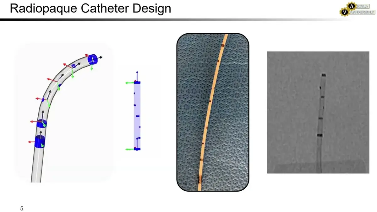
Radiopacity is not a material property that can be added without consequences. A polymer that is easy to extrude, soft enough for a tortuous path, and strong enough for use may become stiffer, weaker in fatigue, less consistent in dimension, or harder to process after radiopacifier is introduced.
The practical goal is not to make every part of a device as bright as possible under fluoroscopy. It is to provide clear, repeatable visibility at the clinical locations and imaging conditions that matter, while preserving the device’s required mechanical behavior and manufacturability. That requires choices about filler chemistry, particle characteristics, loading level, polymer, geometry, and the way radiopacity is distributed through the device.
Start with the imaging requirement, not a filler percentage
A radiopaque formulation attenuates X-rays more strongly than surrounding tissue, producing contrast on a fluoroscopic or radiographic image. However, the visibility of a component is determined by the full imaging situation, not just its formulation.
Before specifying a filler, define these conditions:
- Anatomical location and depth. A component used deep in the body generally needs more attenuation than one close to the surface.
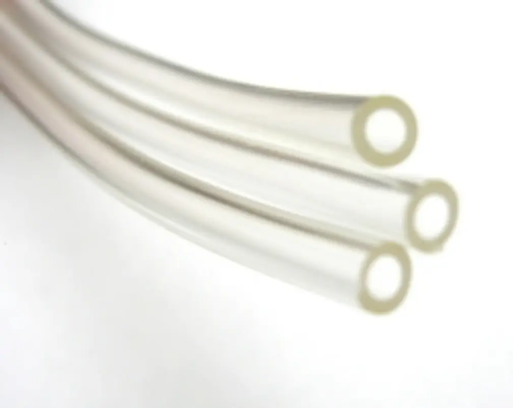
- Device geometry. A thin-wall microcatheter has less material in the X-ray path than a thicker tube, so it may need a more efficient radiopacifier, a higher loading, or a different visibility strategy.
- Fluoroscopy system and exposure range. Beam energy, filtration, image processing, detector performance, and operating technique all influence apparent contrast. A formulation that looks adequate on one system may not perform the same way on another.
- What must be seen. The operator may only need the distal tip, balloon ends, transition point, or a few reference locations. Continuous shaft visibility is not always necessary.
- Background anatomy. Visibility against soft tissue, bone, contrast media, or other instruments can differ substantially.
- Acceptance criterion. Replace a broad requirement such as “highly radiopaque” with a defined test article, imaging setup, orientation, anatomical model or phantom, and pass/fail assessment method.
This definition prevents a common development failure: increasing filler content to solve an imaging issue that is actually caused by a very thin geometry, an unsuitable test setup, or a need for localized markers rather than a fully compounded shaft.
How common radiopacifiers differ
High atomic number and density generally improve X-ray attenuation, but they do not by themselves determine the final formulation. The filler’s density, particle size distribution, particle shape, surface treatment, dispersion behavior, and interaction with the selected polymer all matter.
| Radiopacifier approach | Typical reason to consider it | Main formulation and processing considerations |
|---|---|---|
| Barium sulfate | Widely used, broadly available option for compounded medical polymers | Often requires substantial loading for demanding thin-wall or deep-body applications; increasing volume fraction can reduce elongation and toughness |
| Bismuth compounds | Higher contrast per unit filler volume than barium sulfate in many applications | Particle handling and dispersion need close control; thermal stability and compatibility should be assessed for the intended polymer and process |
| Tungsten | Very high density and strong radiopacity for small or thin features | Heavy particles can be difficult to disperse and may increase melt-processing demands, compound density, abrasion, and cost |
| Tantalum | High radiopacity with established use in metallic radiopaque components | Frequently used as markers or bands; polymer compounding suitability depends on powder form, particle characteristics, and the process window |
| Chemically bound radiopaque groups | Radiopacity introduced through polymer chemistry rather than dispersed inorganic particles | Can avoid some filler-related interfaces, but polymer synthesis, molecular design, extractables assessment, processability, and material availability become central constraints |
Barium sulfate: a practical baseline, not an automatic answer
Barium sulfate is commonly selected because it is familiar in medical polymer compounding and can provide useful contrast in many tubing applications. It is often a sensible starting point when the device can tolerate moderate filler loading and the required visibility is not extreme.
The limitation is that achieving stronger visibility by simply adding more barium sulfate can consume a meaningful fraction of the polymer volume. As filler volume increases, there is less continuous polymer phase to carry strain. The compound may become stiffer, show lower elongation at break, and lose resistance to bending or repeated flexing. In soft polyurethane or polyamide tubing, the change in feel and kink behavior can be significant even where tensile strength remains acceptable.
Barium sulfate is therefore often well suited to larger-wall sections, moderate-contrast shafts, or a radiopaque stripe where a concentrated feature can deliver useful imaging contrast without filling the entire cross-section.
Bismuth compounds: more contrast at lower volume, with compounding discipline
Bismuth-based radiopacifiers are denser than barium sulfate. That can allow an engineer to achieve a target contrast with less filler volume, even if the weight percentage appears high. This distinction matters: mechanical effects often track filler volume fraction more directly than filler weight fraction.
Bismuth compounds can be useful when a barium sulfate formulation would need so much filler that flexibility or toughness is compromised. They still require careful formulation. Poor dispersion creates localized filler-rich regions that can act as stress concentrators, produce nonuniform visibility, and contribute to surface defects or inconsistent dimensions.
For a candidate bismuth compound, evaluate the specific chemical form rather than treating “bismuth” as one material category. Confirm thermal behavior during compounding and extrusion, powder handling requirements, particle morphology, supplier controls, and the safety evidence required for the intended device contact and duration.
Tungsten and tantalum: efficient radiopacity with different manufacturing costs
Tungsten is attractive when a small, thin feature needs strong visibility. Its high density can make it useful for thin-wall tubing, microcatheter regions, or concentrated radiopaque stripes. The same density also creates processing concerns. Particles can settle during handling, increase compound density, raise equipment wear, and make uniform distribution harder to maintain. High loading may also affect melt flow and dimensional control.
Tantalum is particularly familiar in discrete metallic markers, such as marker bands or coils placed at a catheter tip or balloon location. In polymer formulations, its suitability depends on the powder grade and the ability to compound it without damaging the polymer or creating defects. A metal powder should not be assumed to behave like a fine mineral filler simply because both provide radiopacity.
In either case, evaluate density-related manufacturing effects early. A formulation may look promising in a small laboratory batch but create feeding, segregation, or residence-time problems at production scale.
Chemically bound radiopaque groups: reducing one set of tradeoffs
A chemically radiopaque polymer incorporates radiopaque atoms or groups into the polymer structure rather than relying entirely on dispersed particles. Iodinated polymer systems are a commonly discussed example. This approach may reduce the particle-polymer interfaces that can lower ductility or initiate cracks in filled systems.
It does not remove development work. The modified polymer may have a different glass transition, melt viscosity, moisture sensitivity, bonding behavior, color, sterilization response, or extractables profile than the base material it replaces. It may also be harder to source at medical-device volumes. The value of this route is greatest when particle-filled formulations cannot meet a critical thin-wall, flexibility, or surface-quality requirement.
Why more filler changes mechanical performance
Radiopaque particles do not reinforce every polymer in the way a purpose-designed fiber reinforcement might. In flexible medical tubing, they often disrupt the polymer matrix and create interfaces where stress concentrates.
The most common changes at higher loading are:
- Higher hardness and flexural stiffness
- Lower elongation at break
- Lower tear resistance or resistance to crack growth
- More sensitivity to bending fatigue and repeated flexing
- Reduced kink resistance in thin, flexible constructions
- Changed tensile behavior, including lower ultimate strength in some systems
- Increased density and component weight
- Greater variation when dispersion is not uniform
The result depends on the base polymer. A soft TPU, a high-durometer TPU, a polyamide, a polyether block amide, and a silicone-based system will not respond in the same way to the same filler. Polymer grade, molecular weight, additives, and processing history also matter.
Do not use hardness alone as a screening measure. A filled compound may meet a target Shore hardness yet fail a clinically relevant bending, torque, kink, burst, tensile, or fatigue requirement. Test the finished geometry where possible, because a material coupon does not reproduce multilayer construction, thin-wall cooling history, reflow, bonding, or the stress state in a finished distal section.
Loading should be considered by volume as well as weight
Formulation discussions often use weight percent because it is convenient for batching. It can be misleading when comparing fillers with very different densities.
A dense filler can have a high weight percentage while occupying a smaller volume of the compound than a lower-density filler at the same weight percentage. That may help preserve polymer continuity and flexibility. Conversely, a lower-density filler can occupy enough volume to create a substantial mechanical penalty before its weight percentage appears especially high.
For each formulation candidate, calculate and document:
- Filler weight fraction.
- Estimated filler volume fraction.
- Compound density.
- The resulting wall thickness and component mass.
- The mechanical property changes in the finished component.
This makes comparisons between barium sulfate, bismuth compounds, and metal powders more meaningful. It also helps procurement and manufacturing teams understand why two materials with the same stated loading may process very differently.
Use geometry and construction to avoid overloading the whole device
Full-length compounded radiopaque tubing is only one design option. Often, it is not the most efficient one.
Localize radiopacity where it provides clinical information
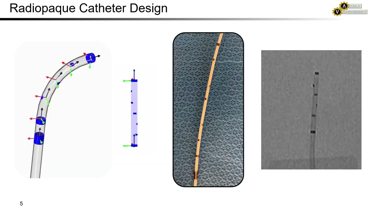
If the user needs to identify the distal tip, working length, balloon ends, or a transition between functional sections, discrete markers may work better than a fully filled shaft. Marker bands, coils, rings, short radiopaque segments, and radiopaque adhesive features can provide strong landmarks without changing the mechanics of the entire device.
This approach requires careful attention to transitions. A sudden change in stiffness can create a hinge point or local stress concentration. Design the overlap, wall transition, bonding region, and edge geometry to avoid a sharp mechanical discontinuity.
Use co-extruded stripes or layers
A radiopaque stripe can preserve much of the flexibility of a radiolucent tube while providing a visible line or orientation cue. A multilayer construction can similarly place the filled compound in a limited layer rather than the entire wall.
The design must still account for interface adhesion, concentricity, stripe placement, and the behavior of the structure during bending and bonding. A stripe that migrates, varies in thickness, or separates from the base layer can affect both imaging consistency and mechanical reliability.
Blend fillers when a single filler forces excessive loading
A blend of radiopacifiers can sometimes achieve the required attenuation profile with less compromise than one filler alone. For example, a formulation may use a base filler for general contrast and a denser component to improve visibility under the intended imaging energy.
Blending is not automatically beneficial. Each added material increases the number of variables in supplier control, compounding, testing, and change management. Use it when measured imaging and mechanical data show a clear advantage over simpler options.
Processing controls that protect performance
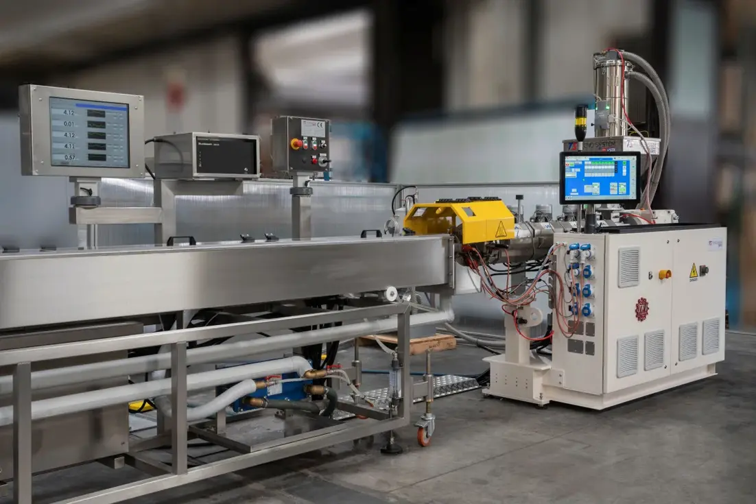
Radiopaque compounds should be developed as process-specific materials. A formulation that looks uniform in pellets can still produce streaks, gels, agglomerates, surface roughness, or dimensional variation after extrusion or molding.
Key controls include:
- Particle specification: Define particle size distribution, morphology, purity, moisture limits, and any surface treatment.
- Dispersion method: Select mixing conditions that distribute particles without excessive polymer degradation or particle damage.
- Drying and handling: Control moisture according to the base resin requirements and prevent powder segregation during feeding.
- Melt temperature and residence time: Avoid thermal degradation while ensuring enough mixing and stable melt flow.
- Screen packs and filtration: Use them carefully. They may remove agglomerates but can raise pressure, retain filler, or increase shear.
- Tooling and equipment wear: Abrasive or high-density fillers can affect screws, barrels, dies, and metering consistency over time.
- In-process checks: Monitor outer diameter, inner diameter, wall thickness, concentricity, stripe geometry, surface appearance, and material density where useful.
A process validation plan should include worst-case conditions likely to affect dispersion and dimensions, not only nominal settings.
Build the verification plan around the tradeoff
Radiopacity and mechanics should be verified together across the intended design space. A strong test plan links the material specification to the clinical imaging requirement and the finished device requirements.
For imaging, assess the actual component under defined fluoroscopy or radiography conditions. Include the relevant wall thickness, orientation, anatomical depth simulation where appropriate, and background materials. Compare candidate formulations at realistic exposure settings rather than relying only on a single bench image.
For mechanics, select tests that match device risks. Depending on the component, that may include tensile testing, bend or kink testing, torque response, burst pressure, bond strength, flexural fatigue, abrasion, and simulated-use cycling. Examine both average performance and variation between lots, extrusion runs, and component positions.
Also assess downstream operations. A filled tube may behave differently during thermal bonding, tipping, drilling, laser processing, overmolding, adhesive bonding, or sterilization. These effects can be more important than the initial tensile result.
A practical formulation workflow
- Define the visibility task. Identify exactly which device feature must be seen, under which imaging conditions, and at what anatomical depth.
- Set mechanical and process limits. Establish measurable requirements for flexibility, kink resistance, tensile performance, fatigue, dimensions, bonding, and manufacturing yield.
- Select a small material matrix. Compare at least one practical baseline, such as barium sulfate, with one higher-density option if the geometry is thin or the visibility requirement is demanding.
- Compare on a volume basis. Record weight fraction, calculated volume fraction, density, and finished wall geometry.
- Make representative parts early. Test extruded or molded components, not only compounded pellets or plaques.
- Use localized designs first where feasible. Evaluate marker bands, short radiopaque sections, stripes, or filled layers before increasing filler throughout a long flexible shaft.
- Confirm repeatability. Verify imaging and mechanical performance across production-relevant processing conditions and material lots.
The central radiopaque polymer formulation tradeoff is simple: more attenuation usually costs something in mechanics or processability. The solution is rarely a maximum filler loading. It is a formulation and device construction that puts sufficient contrast at the required location, under the required imaging conditions, while leaving as much of the polymer’s original function intact as possible.