Medical Devices, Materials, Design & Development, Manufacturing, Quality & Testing
Ultrasonic Welding Problems and Solutions in Medical Device Manufacturing: Troubleshooting Inconsistent Welds, Flash, Cosmetic Defects, and Contamination
Updated
Introduction
Ultrasonic welding is a mainstay for assembling plastic components in medical device manufacturing. Its speed and cleanliness make it ideal for applications ranging from tubing connectors to diagnostic housings. Yet, even well-controlled processes face recurring problems: inconsistent weld strength, excess flash, part deformation, visible cosmetic issues, incomplete (cold) welds, and particulate or contamination in the weld. These issues not only drive up scrap rates and rework costs—they can jeopardize device reliability and delay regulatory compliance.
This article focuses on practical, stepwise troubleshooting for the most common ultrasonic welding problems in medical manufacturing. It covers typical root causes, how to isolate and diagnose them, and specific corrective actions for process engineers, quality professionals, and product developers.
1. Inconsistent Weld Strength
Symptoms:
- Welds sometimes pass and sometimes fail strength or leak tests
- Failure points jump around the weld line
- Excess variation between lots or shifts
Primary Causes:
- Variation in part dimensions or fit
- Inadequate or unstable fixturing
- Variability in applied pressure, amplitude, or weld time
- Material inconsistency (e.g., resin batches or drying)
Troubleshooting Steps
Check Part Fit and Alignment
- Inspect molded part tolerances. Parts should nest tightly with minimal gaps or warp.
- Use go/no-go fixtures to confirm consistent geometry.
- Realign horn and fixture if necessary to ensure parallel and centered contact.
Assess Fixturing and Support
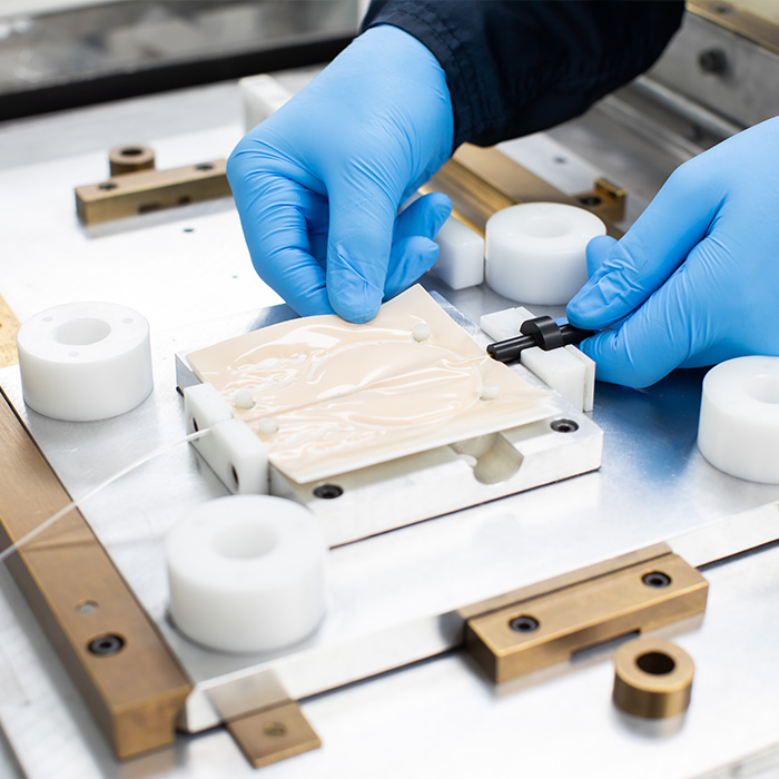
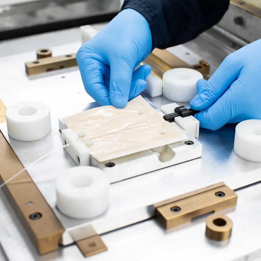
- Rigid, repeatable support directly beneath the weld line is crucial. Movement or flexing absorbs welding energy, reducing consistency.
- Add clamps, nests, or pins to restrain the parts under ultrasound.
Validate Process Parameter Repeatability
- Monitor and, if needed, recalibrate pressure regulators and sensors.
- Ensure amplitude and weld time settings do not fluctuate, especially during shift or equipment changeovers.
- Audit machine maintenance; horns and boosters must be checked and serviced for wear and cracks.
Review Material Consistency
- Check for variation in resin or compounded batches, filler content, or moisture (especially in hygroscopic plastics).
- Keep resin lots consistent for medical production. Ensure materials are within shelf-life and dried to the specified moisture.
Run Statistical Tests
- Conduct pull, peel, or burst strength tests on multiple continuous samples. Measure both the mean and variation (standard deviation).
- If variation tracks with operator, shift, or environmental changes, root cause may be external to the machine settings.
2. Flash, Deformation, and Overweld
Symptoms:
- Excess plastic flash at the joint line
- Weld area collapsing more than intended
- Deformation or sink on visible surfaces
Primary Causes:
- Too much ultrasonic energy (high amplitude, long time, high pressure)
- Poor joint design (energy director too large, no flash trap)
- Parts not properly aligned or poorly supported
Troubleshooting Steps
Optimize Process Parameters
- Reduce amplitude, pressure, and/or weld time in controlled steps.
- Use less aggressive energy profiles, such as a ramped or stepped approach.
- Lower collapse distance or switch to distance or energy control modes, if supported by equipment.
Revisit Joint Design
- Use optimized energy director dimensions—too tall or wide encourages excess melt and flash. Amorphous plastics often need smaller energy directors than semicrystalline ones.
- Integrate flash traps: add a small channel or cavity beside the weld line to capture overflowed material.
Upgrade Fixturing
- Make sure the part sits flat with no movement during welding. For sensitive or thin-walled parts, use conforming soft materials or pre-load features.
Check Horn/Anvil Condition
- A worn or damaged horn can transmit uneven energy, causing localized flash or marking. Regular inspection and tuning are essential.
3. Cosmetic Defects: Marking, Whitening, or Crazing
Symptoms:
- Visible horn/impression marks
- Stress whitening (appearance of white areas on or near weld)
- Crazing (fine cracks on smooth surfaces)
Primary Causes:
- Excess energy (overweld)
- Incorrect horn surface finish (rough or dirty)
- Improperly polished or misaligned horns
- Too much friction between horn and part
- Horn overheating
Troubleshooting Steps
Adjust Process Controls
- Lower weld amplitude and time. Cosmetic issues are often improved with lower energy and gentler process profiles.
Polish or Coat Horn Face
- A highly polished horn or one with a proper coating minimizes direct sticking and friction marks.
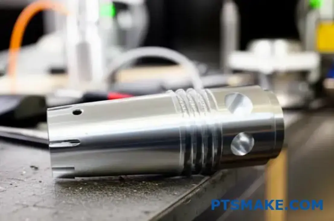
- For high cosmetic requirements, use a coated or chromed horn.
Fix Horn-Part Alignment
- Realign the horn so it perfectly matches the weld area.
- Use fixturing that guarantees repeatable, accurate placement.
Control Horn Temperature
- If horns become too hot, inspect for internal faults, cracks, or excessive duty cycle. Reduce cycle length, or use cooling.
Material Selection
- Amorphous plastics generally produce cleaner welds than semicrystalline alternatives; trial new resin options for visually critical components.
4. Weak or Incomplete Welds (Underweld)
Symptoms:
- Welded parts separate easily by hand or under testing
- Clean interface separation (smooth unmelted joint)
- Seal failures or leaks during validation
Primary Causes:
- Not enough welding energy (too low amplitude, pressure, or time)
- Absence or poor design of energy director
- Poor vibration coupling due to fixture compliance
- Dirty or wet part surfaces
- Incompatible or heavily filled plastic resins hard to weld
Troubleshooting Steps
Tune Up Welding Parameters
- Increase weld time by small increments. If that does not help, increase amplitude and/or pressure.
- For thin-walled or small parts, small changes can have significant effects—avoid overshooting.
Check Joint Design
- Add or optimize energy director. Shape should have a sharply pointed apex and proper size for the resin family.
- Consider switching to a shear joint for semicrystalline materials or when hermeticity is critical.
Clean Parts
- Remove contamination, mold release, and moisture from part surfaces before welding.
- Ensure no surface coatings or static attract dust prior to assembly.
Upgrade Fixture Rigidity
- Replace soft, compliant, or ill-fitting fixtures with rigid metal nests.
Review Material Issues
- Verify all batches of plastic resin are compatible and from approved sources. Check for excessive fillers (>20%) that may impede welding.
5. Non-uniform Welds Around the Joint
Symptoms:
- Weld bead width or appearance changes around the perimeter
- Some spots are strong, others weak or unjoined
Primary Causes:
- Part warpage, mismatched shrinkage, or poor molding control
- Inconsistent horn pressure or poor surface contact
- Inconsistent energy director geometry from mold wear
Troubleshooting Steps
Inspect Molded Parts for Warpage or Dimensional Shift
- Use calipers, fixture gauges, or CMM checks to verify part conformity.
- Audit injection molding process control if dimensionally unstable.
Check for Mold Wear
- Rounded or partial energy directors dramatically reduce local heat generation. Replace or maintain molds to restore intended geometry.
Confirm Stable Horn Contact
- Test multiple placements in the fixture to ensure uniform horn contact and pressure distribution.
6. Contamination and Particulate Generation
Symptoms:
- Visible particles, specks, or residue in or on the weld
- Visual defects inside transparent parts
- Failed particulate or cleanliness inspections
Primary Causes:
- Residual mold release or oils on parts
- Dust or environmental debris in the manufacturing environment
- Overheating causing material breakdown and fumes
Troubleshooting Steps
Enforce High Cleanliness Standards
- Clean parts before welding, using dedicated equipment for sensitive medical devices.
- Perform ultrasonic cleaning for transparent or functionally critical components.
Control Manufacturing Environment
- Conduct welding in a controlled clean area; minimize exposure to ambient air prior to assembly.
- Implement PPE and cleaning protocols for operators.
Avoid Overheating
- Optimize process settings to avoid char or degraded plastic, which releases particulates.
Use Proper Materials
- Avoid heavily filled, regrind, or contaminated resins which are more prone to forming particulates.
7. Summary Table: Problems and Core Solutions
| Problem | Typical Root Causes | Immediate Actions |
|---|---|---|
| Inconsistent weld strength | Poor fit, variable parameters, unstable fixture | Calibrate fit, stabilize setup, audit parameters |
| Flash and deformation | Excess energy, poor joint design | Reduce settings, redesign joint, add flash trap |
| Cosmetic defects | Overweld, friction, horn issue | Lower energy, coat/polish horn, realign |
| Weak/incomplete welds | Low energy, bad joint or fixture, contamination | Increase energy, fix joint/fixture, clean parts |
| Non-uniform welds | Dimensional or tool variation | Inspect parts/mold, maintain equipment |
| Contamination/particles | Dirty parts/environment, overheated resin | Clean parts/environment, optimize heat |
Key Prevention and Best Practices
Design for Ultrasonic Welding Early: Include clear energy directors and flash traps during part and tool design. Consult application engineers and reference known-good joint geometries for your resin type.
Automate Quality Checks: Use mechanical go/no-go gauges or in-line vision for part fit, and monitor weld parameters automatically where possible.
Control Materials and Environment: Maintain a single material supply, control environmental cleanliness, and ensure all operator and process areas are clean.
Document and Monitor Standards: Implement robust instructions for machine setup, preventive maintenance, and change control after process optimization. Track and review weld process data for trends and recurring issues.
By sticking to a methodical troubleshooting sequence—starting with design, moving to fixtures, then process parameters and materials—you can address recurring ultrasonic welding issues quickly and sustain high-quality, reliable medical device production.